

You are using an out of date browser. It may not display this or other websites correctly.
You should upgrade or use an alternative browser.
You should upgrade or use an alternative browser.
Need help setting up drone
- Thread starter Marijn
- Start date
rtkDarling
Well-Known Member
- Joined
- Nov 1, 2018
- Messages
- 746
- Reaction score
- 1,139
- Age
- 41
So to clarify, when you plug it in you don't get 5 tones do you? You probably only get three.
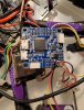
You want this bidirectional switch off (the picture shows it on)

You want this bidirectional switch off (the picture shows it on)


So then you obviously are not getting all 5 start up tones? Only the first 3 I am guessing? The last 2 tones tell you that the FC is talking to the ESC's, without that communication you won't be able to read or write your ESC's. When the FC cannot talk to the ESC's then they can't get "turned on" by the FC or BF ever. Let us know how many startup tones you get and hopefully you have changed to DShot600 for your ESC protocol
Yeah I switched to Dshot600
This is a video of me starting up the drone: VID_20200421_230211.mp4
This is a video of me starting up the drone: VID_20200421_230211.mp4
Yup, you are missing the last 2 tones, so that means your FC is not talking to the ESC's, you need to figure out why. There should be a cable that goes between the ESC and FC with your Signal wires for each motor and a few other things, I would look into that first.
There is a cable missing, or plugged into the wrong place it looks like. On the ESC there is likely a connector that accepts the motor signal wires, I think I see it but the video is too short and not pointing in the correct place for me to see enough. You only have the 5 volt and ground wires (the red and black) and you are missing something major that should connect the 2. Look close on the FC and ESC and you should see connectors that have either a 1, 2, 3, 4 or a S1, S2, S3, S4 on it (and probably a few other things) in the silk screening on the boards. If you can get very clear pictures of the top and bottom of the FC and ESC I may be able to point you in the right direction.
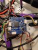
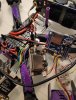
So here are some pictures of my FC and the ESC. I couldn't get a picture of the back of the ESC, but it is this one: Eachine Wizard X220S FPV Racer RC Drone Reserveonderdeel 4 in 1 30A ESC BLHeli_S 2-5S Dshot600 RC delen from Speelgoed, Hobby's en Robot on banggood.com (My FC is the omnibus F4 V3 btw)
I hope this helps.
Btw, I really appriciate you guys helping. I can't thank you enough!
I hope this helps.
Btw, I really appriciate you guys helping. I can't thank you enough!
Attachments
I might have an idea what's wrong. I think it is weird that the esc is connected to the videotransmitter. Is this the problem?
Hey @Marijn, no thanks needed, you getting in the air is all the thanks we need!
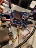
Ok, here is what I see...
In this pic, there are 2 vTX's that I have circled, this is wrong since you can only have 1.
The arrow that points to the cable to the vTX on the lower left side of the picture looks like the cable that is plugged into the wrong place and I believe may really go to one of the connectors on the FC but I will need to look at this more. How do you think you ended up with 2 vTX's in this thing?
Pretty sure that it is, but be careful, we don't guess in this hobby because that leads to mistakes and blown hardware. First lets figure out how you got 2 vTX's in this thing, and let me see where that cable belongsI might have an idea what's wrong. I think it is weird that the esc is connected to the videotransmitter. Is this the problem?
YESSSS!!!!! I got it to work. I plugged the cable that went from the ESC to the VTX into the FC!
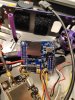
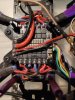
As you can see in this pic of your ESC, the silk screening on the board says that these are you motor 1234 and a + and - (5 volts and ground), this is likely how your FC is SUPPOSED to get its power and the ESC gets the motor signal wires from the FC. I am now wondering what the big Red and Black wires are for, probably so the FC can sense what your battery voltage is but I am still investigating that part.

There is NO WAY it came with 2 vTX boards, either there is something that I am missing, or... not sure. All I can say is you still have to get EVERY needed feature to work and then button it all up inside the frame for flight.
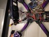
So I connected the wire from the ESC to this port on the FC

Now the motors can rotate in BF and with my transmitter
Now the motors can rotate in BF and with my transmitter
Not those, the 2 next to it that go to the FC, I can now confirm that is the way the FC gets the battery voltage level so it can put it into the OSD and Telemetry infoThe big red and black cables are connected to the battery
Similar threads
- Replies
- 0
- Views
- 418
- Replies
- 0
- Views
- 597
- Replies
- 0
- Views
- 731
- Replies
- 0
- Views
- 607